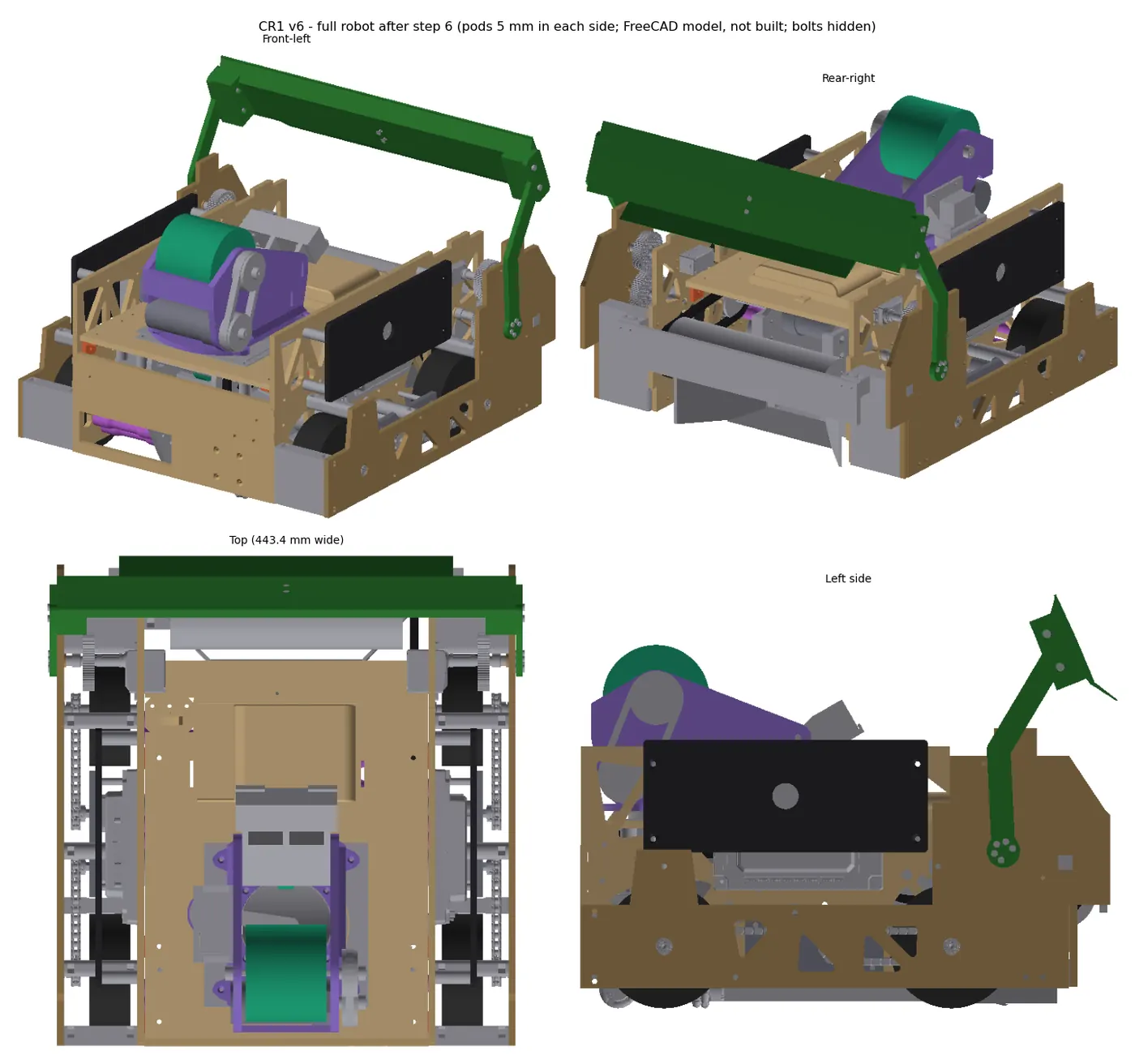
We design the whole robot in CAD and make most of it ourselves: plywood and aluminum plates on a laser cutter, and custom parts on 3D printers. This page shows the robot we are building for the qualifier on December 20.
Scores Pollen
Topspin shooter on a turret
443 × 453 × 357 mm (18 in = 457 mm)
How it works
A roller at the front picks Pollen off the floor. The ball waits in a 4-ball lane down the middle of the robot. A pair of wheels squeezes it up into the shooter head, where a spinning wheel on top launches it with topspin, so it rolls into the hive instead of bouncing out. The head sits on a turret that turns ±90°, with a camera on top to aim. A wedge at the front slides under Pollen in the flower so it rolls out to the intake.
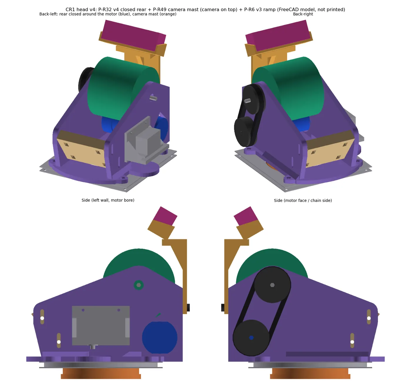
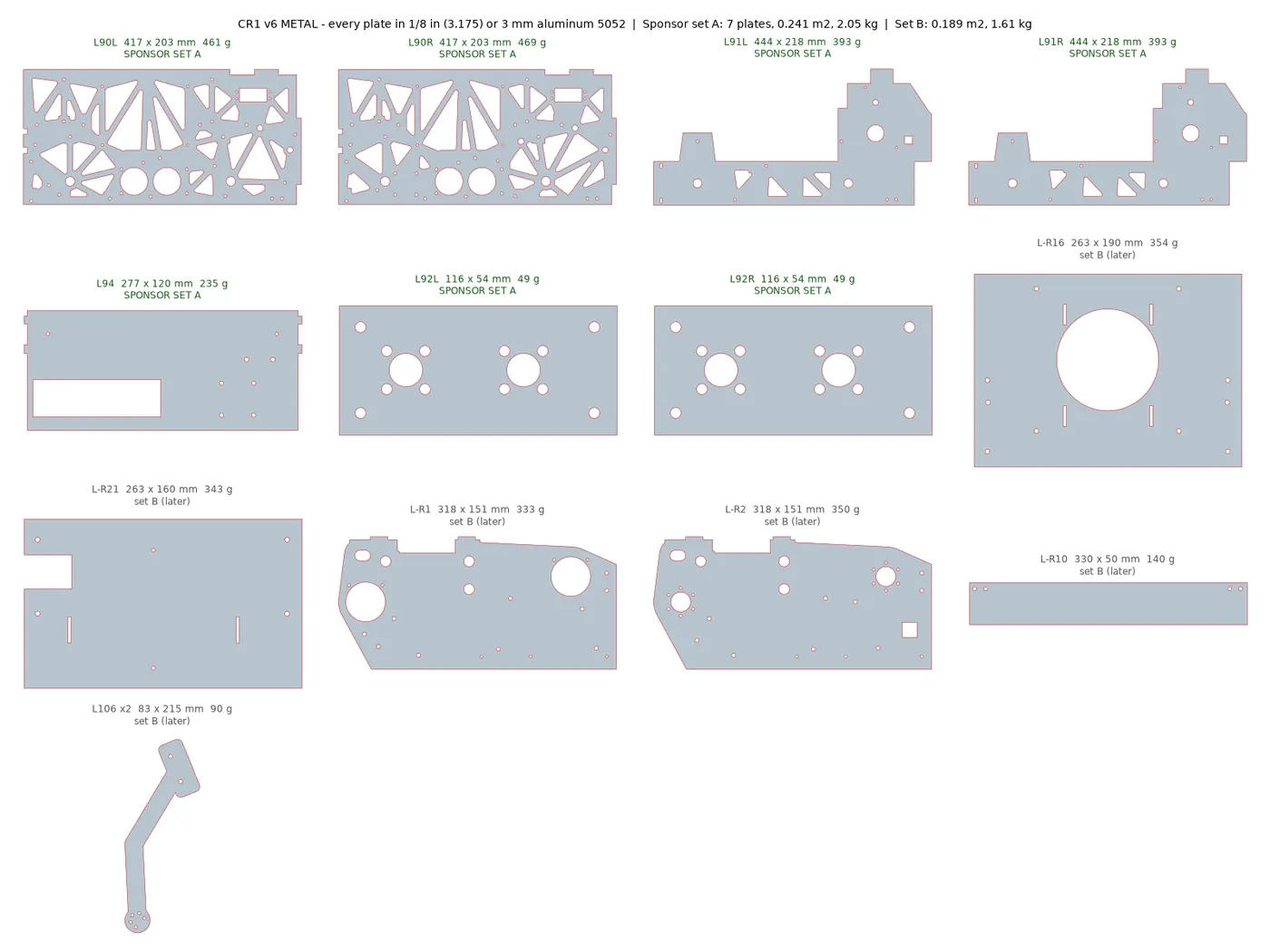
CR1 v6 in CAD, Nov 17 (EN-108). Since then the side plates went to aluminum, the lane became two prints, and the camera moved to the top of the head (below).
Part
What it is now
Status
Drivetrain
Two pods, each with 2 goBILDA motors, chain drive and 104 mm mecanum wheels. Full-length side plates; the main plates in 1/8 in aluminum. EN-107 · EN-108 · EN-111
Files ready
Intake + lane
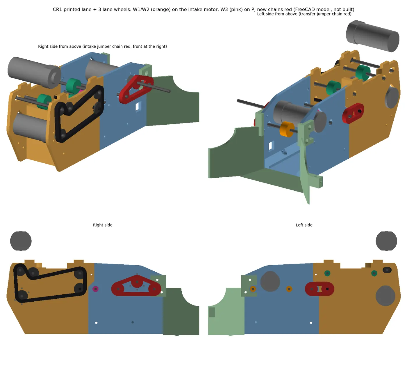
A tubing roller touches every ball first. A plate keeps Nectar out. The lane is two 3D prints and holds 4 balls, with 3 small wheels so a ball never sits still. EN-112 · EN-113
Files ready
Transfer
A front and a back wheel squeeze the ball up into the head, on one motor with one chain. EN-105
Files ready
Shooter head
One printed piece. Flywheel on top, grippy 55° ramp under the ball, motor tucked behind and under the wheel. A servo gate holds the ball until we fire. EN-102 · EN-103 · EN-114
Rig shot well final print not made
Turret + camera
A 6 in lazy susan turned by 2 REV servos, ±90°. A webcam on a mast on top of the head. EN-104 · EN-114
Files ready
Flower wedge
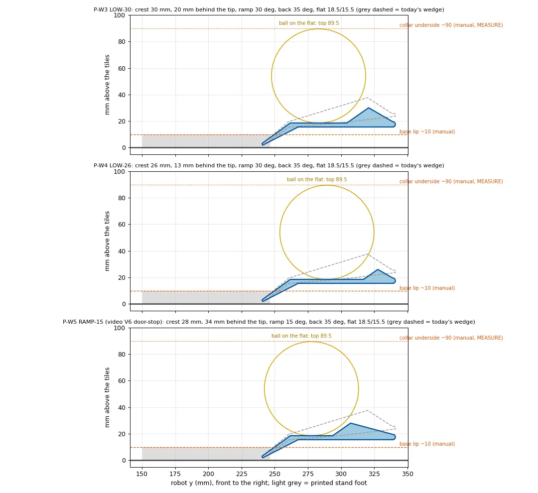
A full-width wedge on two short arms outside the pods, moved by a servo. Three low shapes to test on the real flower. EN-100 · EN-115
Test slices ready
Electronics
Control Hub and Expansion Hub inside the pods, a recessed power switch, the Pinpoint odometry sensor flat on a printed shelf. EN-99 · EN-110
Files ready
Honest status: CR1 v6 is fully designed and checked in CAD (no parts clash, the ball path is clear, it fits the 18 in box). It is not built yet. The topspin head was tried on a bench rig and shot much more consistently than our old hood shooter. Next: cut, print, build, then test with counts. What's next
1/4 in plywood for plates and panels. Our Falcon A1 bed is 305 × 381 mm, so early plates were split with seams that step around bolt holes. EN-01
The CR1 v6 side plates are longer, so we cut them whole on a bigger Glowforge (495 × 279 mm bed). EN-107
Plates are pocketed with straight struts between the holes we use, so they are light but strong. EN-95
The sponsor plates are cut in 1/8 in aluminum from the same files. EN-111
3D printers
PLA on a Bambu A1 and P1S, both with a 256 mm bed. Every print is designed to fit it.
We print whole assemblies as one part when we can: the shooter head (9 parts to 1), the robot signs (16 to 1), the lane (7 to 2). EN-102 · EN-106 · EN-112
Before a big print we print small test coupons for hole and joint fit.
Fasteners
Wood joints use #8-32 bolts with lock nuts, and REV parts use M3. Plates join with printed corner brackets, not nuts hidden in plate edges. No bolt head or nut is allowed in a ball's path. EN-03 · EN-77
Every change follows the same steps
Change the model in CAD.
Check for clashes, so no two parts overlap, every screw can be reached, and the robot still fits inside 18 inches.
Test the risky part on a bench rig before the whole robot.
Export the files: laser files for plates, STL files for printing.
Write it up in our engineering notebook: the problem, the numbers, the options and the result.
Control
What each sensor does, the problem it solves, and how it works. No code needed to follow it.
Shooter speed control
Sensor: the encoder on the flywheel motor counts how fast it turns.
Problem: with a fixed power, the wheel slows when the battery runs low and after each shot, so shots land in different places. Our study found that just 3% too fast or slow loses half of the distance range where we score.
How it works: we set a target speed. Many times a second the Control Hub compares the real speed with the target and adds or takes away power (a PIDF loop). FTC Dashboard draws live graphs so we can tune it.
Status: the code builds; tuning waits for the robot. EN-43 · EN-90
Knowing where the robot is
Sensors: the goBILDA Pinpoint odometry computer, the drive motor encoders and the gyro in the Control Hub.
Problem: in autonomous nobody drives, so the robot has to know where it is on the field.
How it works: our drive code (Road Runner) adds up how far the robot moved and which way it faces.
Status: the Pinpoint has a printed shelf on CR1 v6; no tuning results yet. EN-99
Aiming the turret
Two REV servos turn the turret through printed gears, ±90°. The webcam on top of the head looks forward, 30° up, so it can see the field's tags. The plan is to use the camera to point the turret at the hive. This code is not written yet. EN-103 · EN-114